Reset Arduino Programmatically

Amazing 3 dimensional LED display.
64 LEDs makes up this 4 by 4 by 4 cube, controlled by an Atmel Atmega328 microcontroller [I’m using an Arduino UNO]
Each LED can be addressed individually in software, enabling it to display amazing 3d animations!
Step 1: You Will Need

First of all, you need quite a bit of time to solder together 64 leds
Knowledge list:
-
- Basic electronics and soldering skills
- Know how to use an Arduino, programming an Arduino.
Component list:
- An Arduino. The code supplied assumes an Arduino Uno, but could be adjusted to a larger model too.
- 64 LEDs – the exact choice is up to you, but I used these superbright 3mm Blue LEDs
- 16 Resistors of the appropriate value for your LEDs. Use ledcalc.com – enter 5v for the supply voltage, the voltage of the LEDs (in my case 3.2) and the current in milliamps (3.2). Your desired resistor will be shown in the box labelled“Nearest higher rated resistor”,
- Some craft wire to strengthen basic structure and for decoration – I used0.8mmthickness.
- A prototyping board of some type that you can solder all your bits to. I used one which didn’t have full tracks along it as I don’t have a track cutter, but use whatever suits you. An Arduino prototyping shield is a little too small though, unless you really squeeze your LEDs together.
- Random component wire – some network cable strands and some of the prototyping wires from a kit will work fine.
- Crocodile clips or “helping hands” are useful for holding bits in place.
- Soldering iron, and solder.
- Some scrap wood.
- A drill, with the same size bit as your LEDs.
Step 2 : The Principle Of This Design
Before you begin construction, it’s important to have an complete overview of how this thing is going to work so you can improvise and identify errors as you go along. Some LED cubes use a single output pin for every single LED – however in a 4x4x4 cube, that would need 64 pins – which we certainly don’t have on an Arduino Uno. One solution would be to use shift registers, but this is unnecessarily complicated.
In order to control all those LEDs in just 20 pins, we’ll be using a technique called multiplexing. By breaking the cube down into 4 separate layers, we only need control pins for 16 LEDs – so to light a specific LED, we must activate both the layer, and the control pin, giving us a total requirement of 16+4 pins. Each layer has a common cathode – the negative part of the circuit – so all the negative legs are joined together, and connected to a single pin for that layer.
On the anode (positive) side, each LED will be connected to the corresponding LED in the layer above and below it. Essentially, we have 16 columns of the positive legs, and 4 layers of the negative. Here’s some 3D views of the connections to help you understand:


Step 3 : Construction


Soldering grids of 4×4 LEDs freehand would look terrible!
To get 4 perfect 4×4 grids of LEDs, we use a template to hold the them in place.
Since we won’t be using a full metal structure to solder to, we want all the legs of the LEDs to overlap by about a quarter and give rigidity to the structure. Fold the cathode of your LEDs – the side with the flat notch in the head and the shorter leg – over as shown in the diagram. (It doesn’t really matter if you bend it left or right, so long as you’re consistent and it never touches the anode)
I wanted to make the cube as easy as possible to make, so I chose to use the LEDs own legs as much as possible. The distance between the lines in the grid was decided by the length of the LED legs. I found that 25mm (about an inch) was the optimal distance between each led (between the center of each led that is!) to enable soldering without adding or cutting wire.
Find a piece of wood large enough to make a 4×4 grid of 2,5cm on.
- Draw up a 4×4 grid of lines.
- Make dents in all the intersects with a center punch.
- Find a drill bit that makes holes small enough so that the led will stay firmly in place, and big enough so that the led can easily be pulled out (without bending the wires..).
- Drill the 16 holes.
- Your ledcube template is done.
Step 4: Making the cube, solder the layers

We make the cube in 4 layers of 4×4 leds, then solder them together.


Create a layer:
- Put in the LEDs along the back and along one side, and solder them together
- Insert another row of LEDs and solder them together. Do one row at a time to leave place for the soldering iron!
- Repeat the above step 2 more times.
- add cross bracing in the front where the led rows are not connected.
- Repeat 4 times.
Step 5: Making the cube, connecting the layers
Now that we have those 4 layers, all we have to do is to solder them together.
Put one layer back in the template. This will be the top layer, so choose the prettiest one
Put another layer on top, and align one of the corners exactly 25mm (or whatever distance you used in your grid) above the first layer. This is the distance between the cathode wires.
Hold the corner in place with a helping hand and solder the corner anode of the first layer to the corner anode of the second layer. Do this for all the corners.
Check if the layers are perfectly aligned in all dimensions. If not bend a little to adjust. Or re-solder of it’s the height distance that’s off. When they are perfectly aligned, solder the remaining 12 anodes together.
Repeat 3 times.
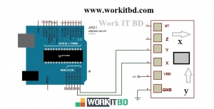
Here is the circuit
For the four negative layers, I dropped a single wire down from each layer, then just pulled them off to the side
Step 6 : Programming Your Cube
Download the demo patterns and code from instructable user forte1994. He’s also provided a helpful online tool for designing the byte patterns to customize your own sequence.
Related Post