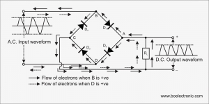
Working principle of Bridge Rectifier

This circuit simulates the police car lights by alternate flashing. This circuit flashes red LEDs for three times and blue LED’s for three times. This flashing action performs continuously.
This circuit uses 555 timer and a decade counter. Here, 555 timer runs in astable mode. Decade counter 4017 counts the incoming pulses that is for first pulse Q0 becomes high and for second pulse Q1 becomes high and so on again for 10th pulse Q0 state becomes high.
555 Timer Based Police Lights Circuit Principle:
Here 555 timer produces continuous pulses via pin 3. The width of these pulses can be varied by varying the resistance (R1,R2 ) or capacitance (C1). These pulses are given as input to the decade counter. For every incoming pulse the output state of the decade counter is get incremented.
- For 1st pulse – Q0 high – blue led’s glow
- For 2nd pulse – Q1 high (no connection) – all led’s off
- For 3rd pulse – Q2 high – blue led’s glow
- For 4th pulse – Q3 high – all led’s off
- For 5th pulse – Q4 high – blue led’s glow
- For 6th pulse – Q5 high – red led’s glow , blue led’s off
- Hence blue led’s flashes for 3 times.
- For 7th pulse – Q6 high – all led’s off
- For 8th pulse – Q7 high – red led’s glow
- For 9th pulse – Q8 high – all led’s off
- For 10th pulse – Q9 high – red led’s glow
- For 11th pulse – Q0 high – blue led’s glow, red led’s off
- Hence red LEDs flash for 3 times. This process repeats continuously.
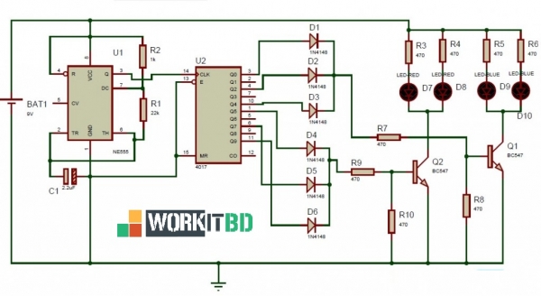
Circuit Diagram of Police Lights using 555 Timer:
Circuit Components:
- NE555 timer
- 4017 decade counter
- 1n4148 diodes – 6
- 1k Resistor(1/4 watt) – 1
- 22k Resistor(1/4 watt) – 1
- 470 ohm Resistor(1/4 watt) – 8
- 2.2uF Electrolytic capacitor(16V) – 1
- Blue LED’s – 2
- Red LED’s – 2
- 9v battery – 1
- Connecting wires
555 Timer based Police Lights Circuit Design:
555 Timer: Here 555 timer runs in free running mode. It produces pulses whose width can be varied. 2nd and 6th pins are shorted to allow triggering after every cycle. 4th pin is connected to Vcc to avoid sudden resets.
4017 Decade Counter: It is a 10 bit counter with ten decoded outputs. It counts the incoming pulses. The supply voltage range is -0.5 to +22V. The high pulse on the reset pin clears the count to zero. The speed of operation of this IC is up to 10 Mhz.
The ouput states (Q0,Q2,Q4) are ORed to flash the blue LED’s 3 times and the states Q5, Q7 and Q9 are ORed to flash the red LED’s 3 times.
Based on the outputs of 4017 IC, two transistors (NPN) switches the LED’s ON and OFF.
Resistors R3, R4, R5, R6 are used to protect the LED’s from high voltage.
How to Operate Police Lights Circuit:
- Apply power to the circuit.
- Now observe the LED’s, red led’s flashes 3 times and blue led’s flashes 3 times and this process repeats.
- If you want to set the different time delays for LED’s then vary the resistance (R1, R2) or capacitance (C1).
555 Timer based Police Lights Circuit Applications:
- This circuit used as an indicator for police cars.
- We can use it as LED flasher circuit by making some modifications.
Limitations of Police Lights Circuit:
- The values of the resistors R1, R2 and capacitor C1 should be same to get perfect flashing.
This Article simillar to - Police siren using NE555
Related Post